Use Case Diagram UML
- A simple but very effective model used during the analysis phase for analysing requirements through the process of exploring user interactions with the system.
- The process involves documenting
- Who initiates an interaction,
- What information goes into the system,
- What information comes out and
- What the measurable benefit is to the user who initiates the interaction (i.e. what they get out of it).
Requirements analysis attempts to uncover and document the services the system provides to the user.
- In use-case modeling, the system is looked upon as a black box whose boundaries are defined by its functionality to external stimuli.
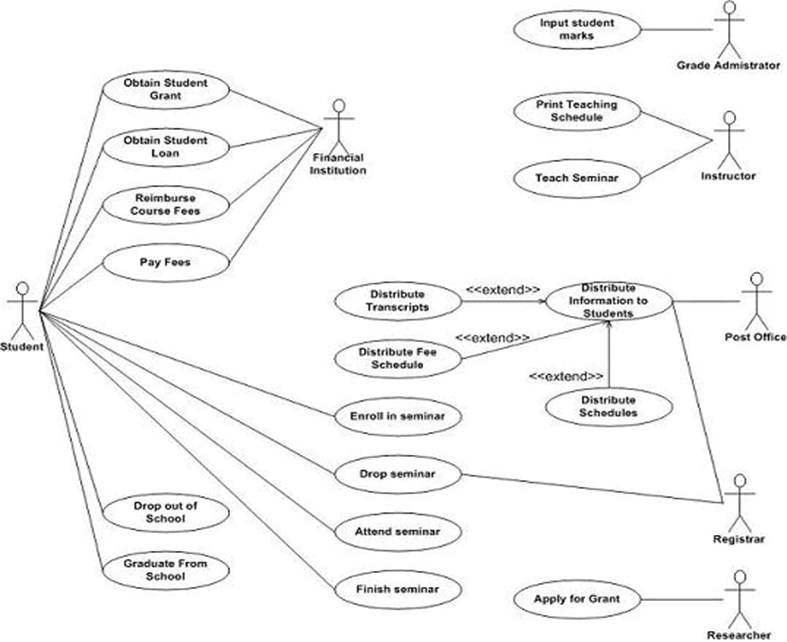
- The actual description of the use-case is usually given in plain text. A popular notation promoted by UML is the stick figure notation.
- We will look into the details of text representation later. Both visual and text representation are needed for a complete view.
- A use-case model represents the use-case view of the system. A use-case view of a system may consist of many Use-case diagrams.
- An use-case diagram shows (the system), the actors, the use-cases and the relationship among them.
- Actions can involve communicating with number of actors as well as performing calculations and work inside the system.
- A Use-case
–is always initiated by an actor.
–provides a value to an actor.
–must always be connected to at least one actor.
–must be a complete description.
Describing Use-cases
- Use-case Name:
- Use-case Number: system#.diagram#.Use-case#
- Authors:
- Event(Stimulus):
- Actors:
- Overview: brief statement
- Related Use-cases:
- Typical Process description: Algorithm
- Exceptions and how to handle exceptions:
Example
- Number: A.132.4
- Name: Buy book online
- Author: B.Ramamurthy
- Event: Customer request one or more books
- System: Amazon.com
- Overview: Captures the process of purchasing one or more books and the transactions associated with it.
- Related Use-case: A.132.5, A.132.8
- Typical Process Description with exceptions handled.
NOTE : All these can be in a tabular form, say, in an Excel worksheet for example.
Practices scenario
–Ticket counter for basketball game
–TIVO: Video recorder/controller
–Weather Station.
–ATM Machine: Description given as data dictionary.
–4-cycle lawnmower engine
–Burger queen fast food restaurant’s hand-held order device
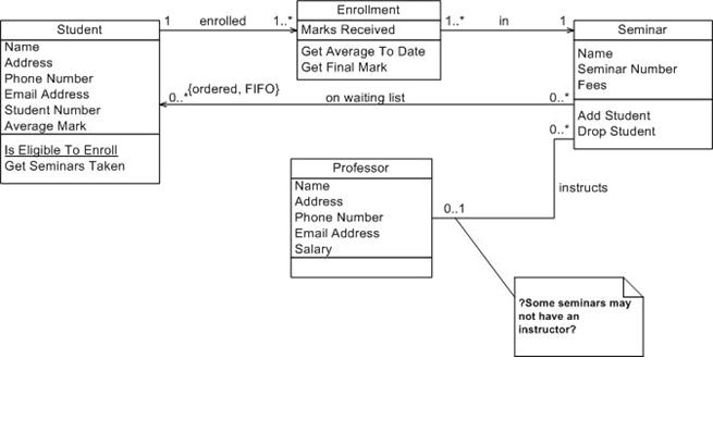
 Class Diagrams:
- A powerful tool for exploring architecture, functionality and relationships between objects in our system (i.e. instances of classes).
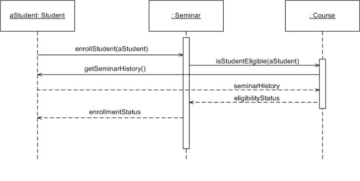
Sequence and Communication (Collaboration) Diagrams:
- These two diagrams model the interaction of a set of collaborating objects through a process of message passing as they attempt to achieve the functionality expressed in one or more use cases.
- In essence they model the behaviour of our system in response to inputs from the external world.